Aerospike Nozzle Design for a Hybrid Rocket
Multidisciplinary capstone project for BASc degree
Overview: Led team of 4 on the design, analysis and integration of a N2O-cooled aerospike nozzle into a small-scale hybrid rocket engine. Developed optimization-based design process to reduce heat loads and maintain thrust, presenting results at CASI ASTRO conference
Supervisor: Prof. Masayuki Yano, Aerospace Computational Engineering Lab, UTIAS
Industry Advisor: Mr. Adam Trumpour, Pratt Whitney Canada
Client: University of Toronto Aerospace Team
What is a Hybrid Rocket?
A hybrid rocket uses a liquid oxidizer and a solid fuel. It combines,
- The mechanical simplicity of a solid rocket
- The high performance of a liquid rocket
The University of Toronto Aerospace Team (UTAT), the clients of this project, build N2O-Paraffin hybrids.
What is an Aerospike Nozzle?
![Aerospike vs bell nozzle comparison [[1]](https://dsiac.org/articles/affordable-access-to-low-earth-orbit/ 'Source')](/media/albums/aerospike/difference_hu228e9b0d0c8069ae068197d57299f96e_202227_5602841f86c520bfdf4d15cbb59fb4d2.webp)
An aerospike is an altitude compensating nozzle which maintains a high efficiency over a wide range of altitudes as opposed to a traditional bell nozzle which is only efficient at a single altitude.
Design Challenges and Overview
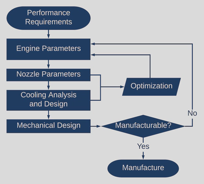
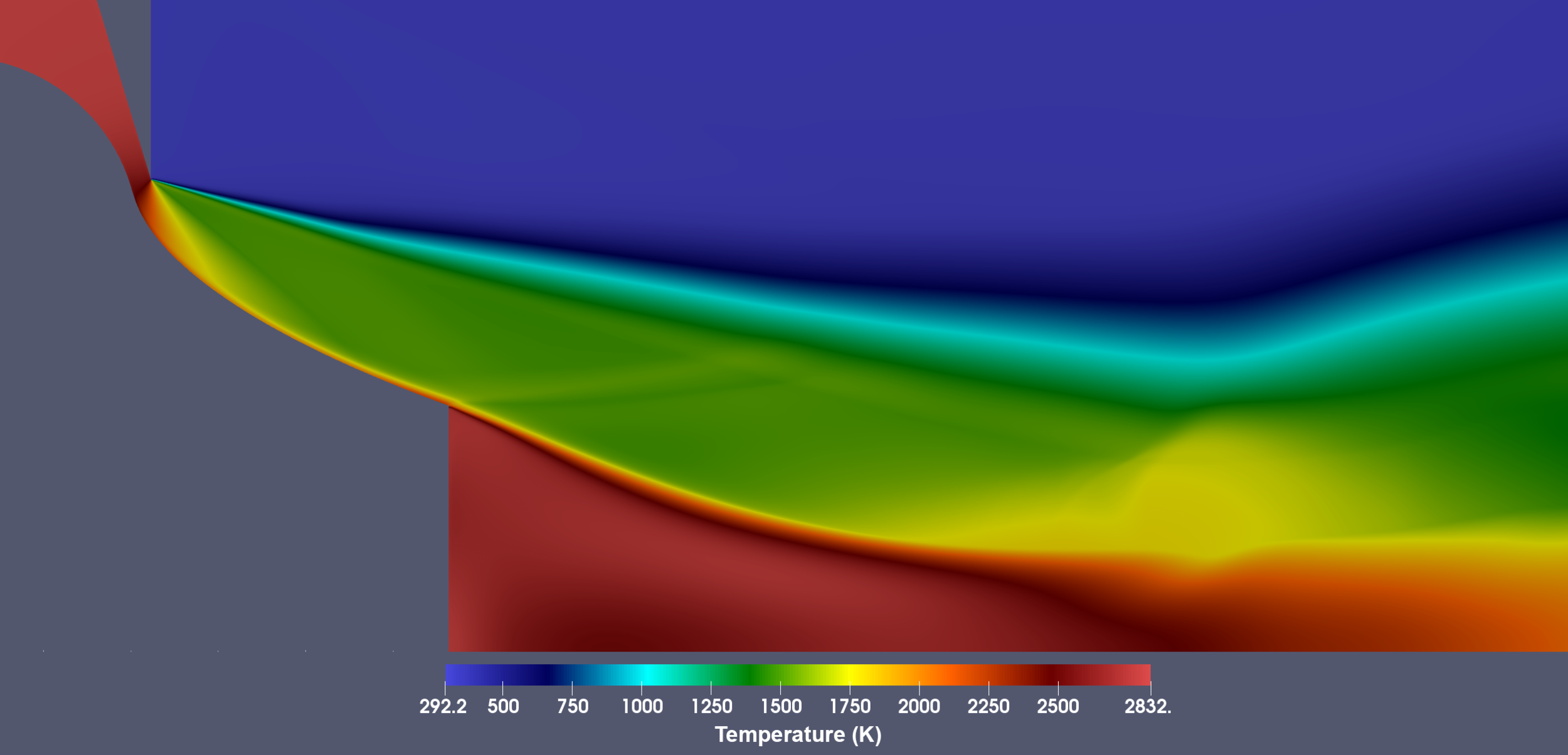
- Few materials withstand the operating temperatures that reach 3000 K
- Complex geometries and large operating pressures pose a mechanical challenge
- A lack of substantial prior art results in the absence of accurate models for predicting key flow transitions
Nozzle Contour
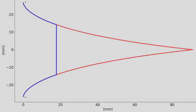
Assuming a Prandtl–Meyer expansion fan at the nozzle throat, the contour was designed through Angelino’s method and truncated to 20% of the original length.
Nozzle Optimization
The optimization cost function that was explored follows, $$ C(\text { contour })=\alpha * \text { thrust }(\text { contour })+\beta * \text { heatduty }(\text { contour }) $$
Computationally inexpensive methods for predicting plume properties and heat transfer (Mayer’s and Method of Characteristics (MOC) respectively) were implemented for iterative optimization.
CFD Simulation
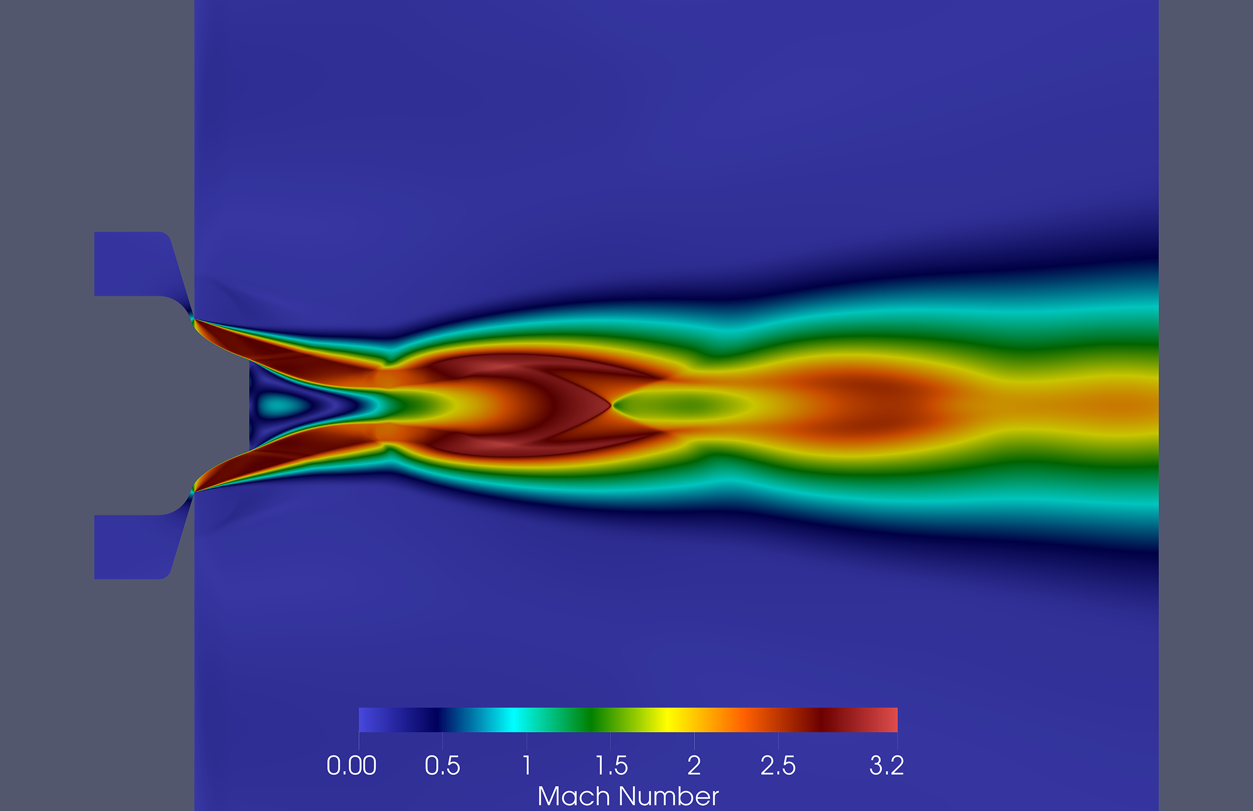
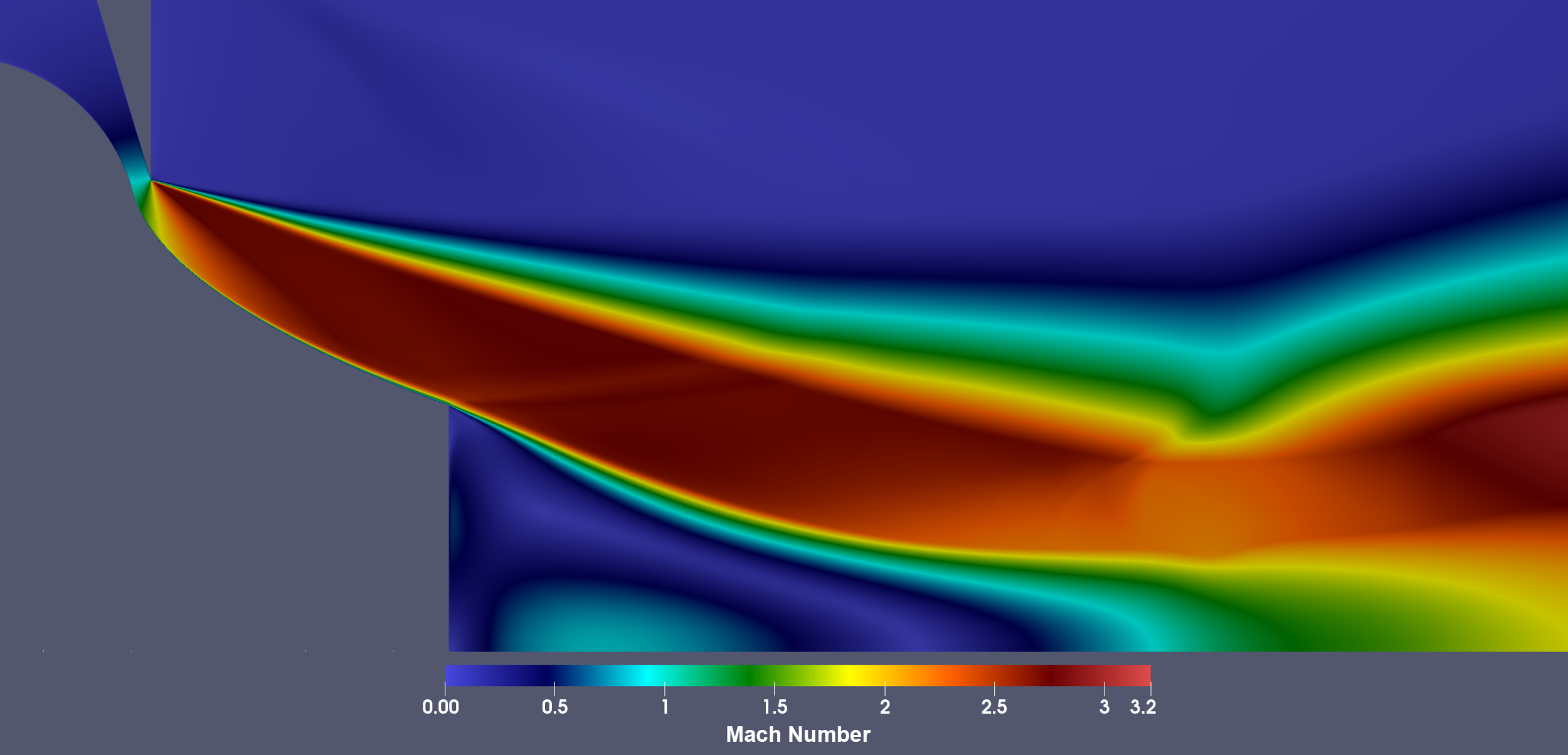
A compressible, viscous, turbulent simulation of the nozzle was run using a density-based CFD solver.
Overview
Throughout the design and optimization process of the aerospike nozzle, a series of lower-fidelity, simplified relations, such as the Method of Characteristics (MOC) or empirical relations for base pressure were utilized for the purpose of rapid prototyping and evaluation. Such low fidelity methods must be validated and for this purpose, the finite difference, computational fluid dynamics (CFD) method was the natural choice for high accuracy flow prediction.
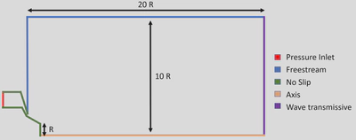
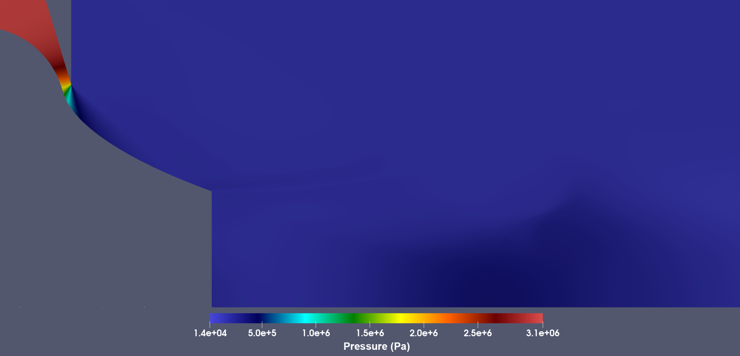
At the inlet, combustion chamber conditions were enforced including a chamber pressure of 450 psi and a temperature of 2831.47 K. Sea level freestream conditions were enforced with an atmospheric pressure and tempearature of 101325 and 298 K respectively. Additionally the freestream outlet had a wave transmissive outflow condition, allowing waves to exit the domain without being reflected. No slip boundary conditions were specified at the nozzle and combustion chamber regions. No inlet or outlet numerical boundary conditions for velocity were provided in order for the flow to be pressure driven and thus induced by the pressure difference between the combustion chamber and the atmosphere.
Configuration
Numerical Solver: Density-based solver using central-upwind schemes proposed by Kurganov and Tadmor
Turbulence Model: High Reynolds Number k-ω SST
Thermophysical Models:
- Equation of state: Ideal Gas Law
- Transport Model: Sutherland
- Thermodynamic Model: Constant Cp = 2015 J/Kg K
- Molecular Weight: 23.1 g/mol
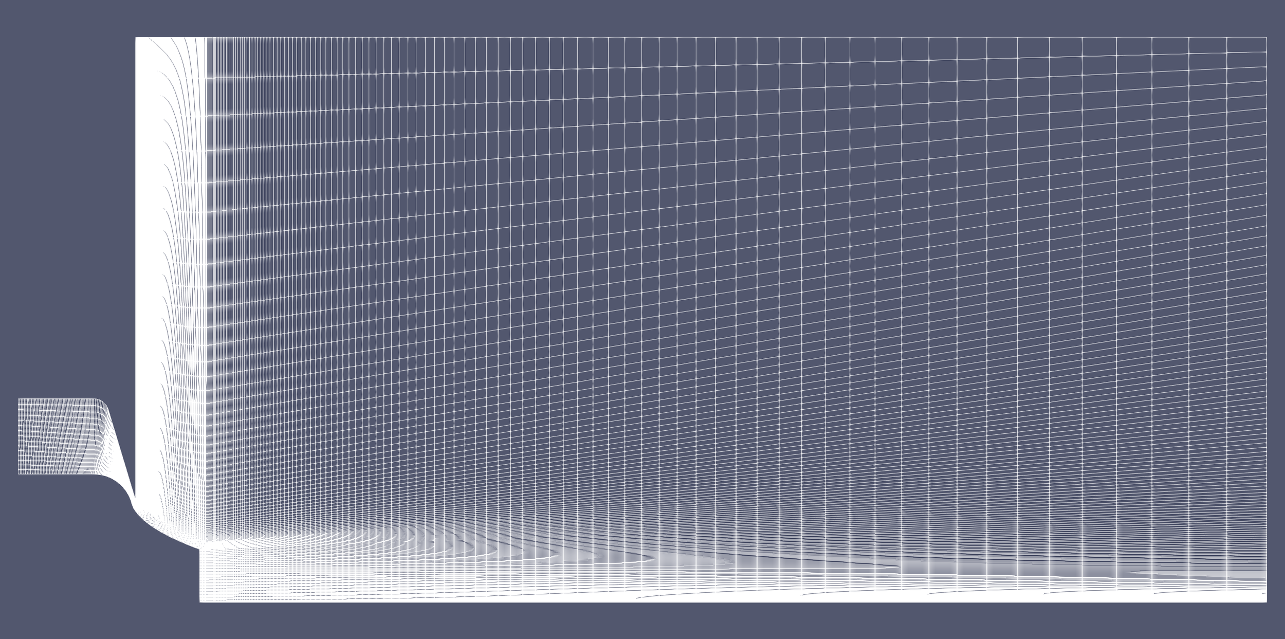
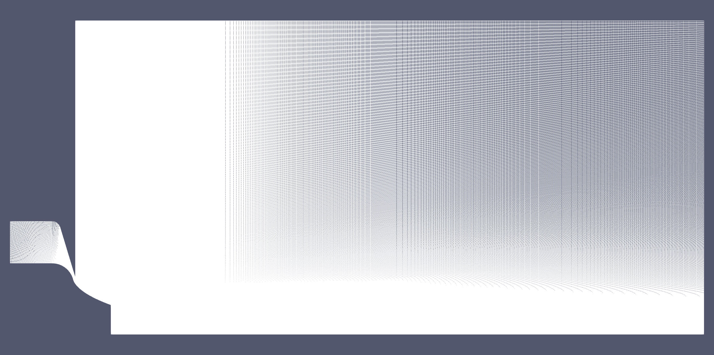
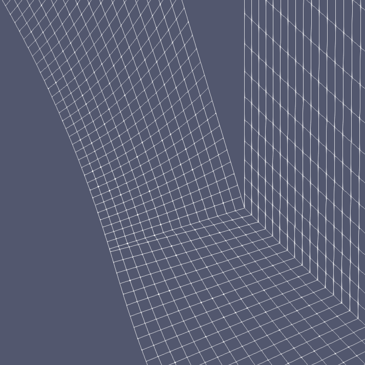
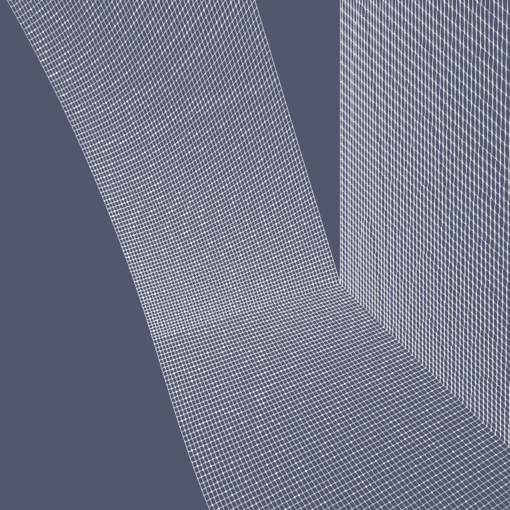
Mesh
Initially a low resolution mesh was utilized in order for the plume to rapidly develop throughout the entire region. Following this, the results were interpolated to a high resolution mesh such that the detailed features of the flow could be resolved.
Low Resolution Mesh
Element number and type: 27,130 hexahedral elements
Average orthogonal mesh quality: 0.84
High Resolution Mesh
Element number and type: 912,120 hexahedral elements
Average orthogonal mesh quality: 0.91
CFD Results - Overview
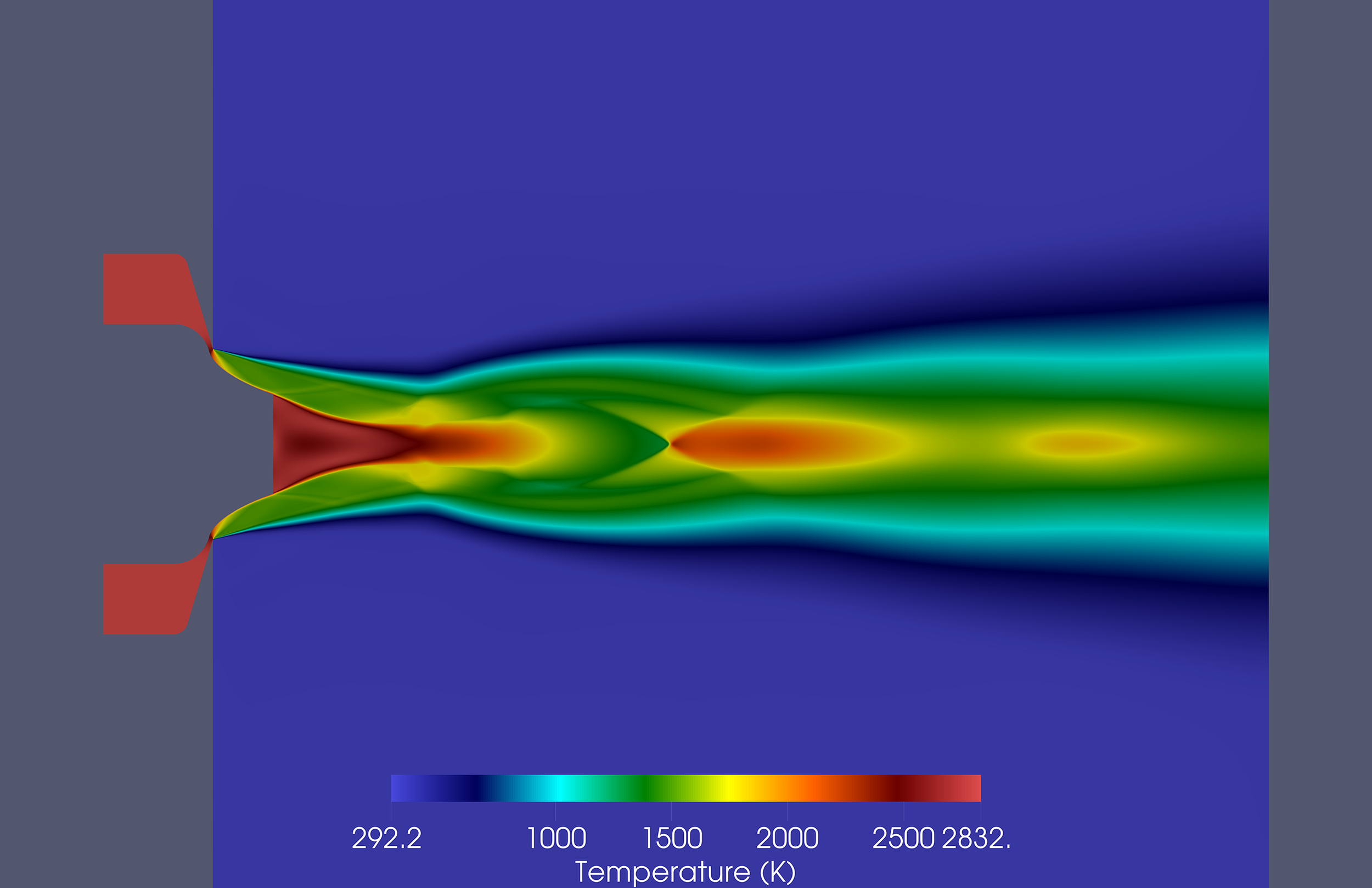
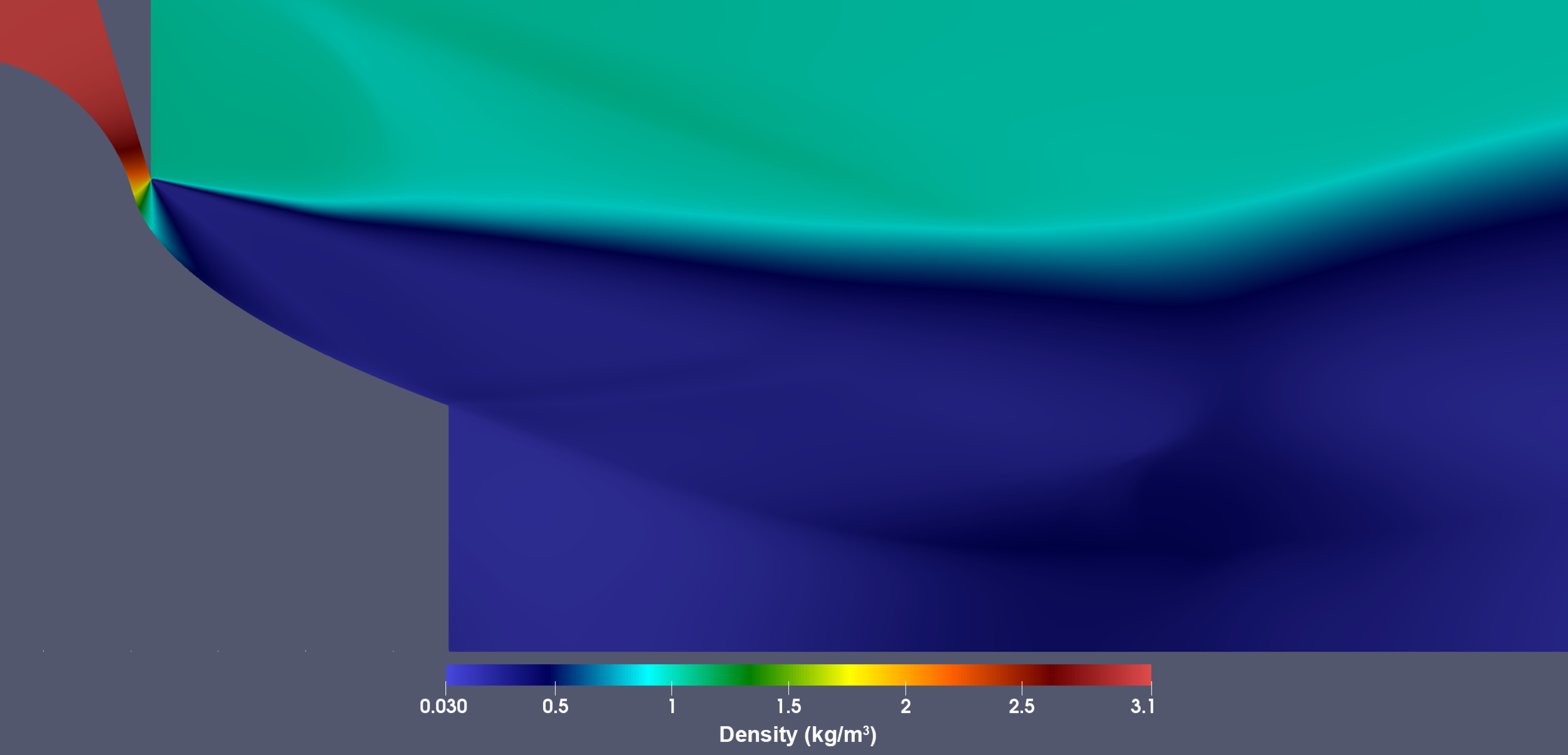
CFD Results - Detailed
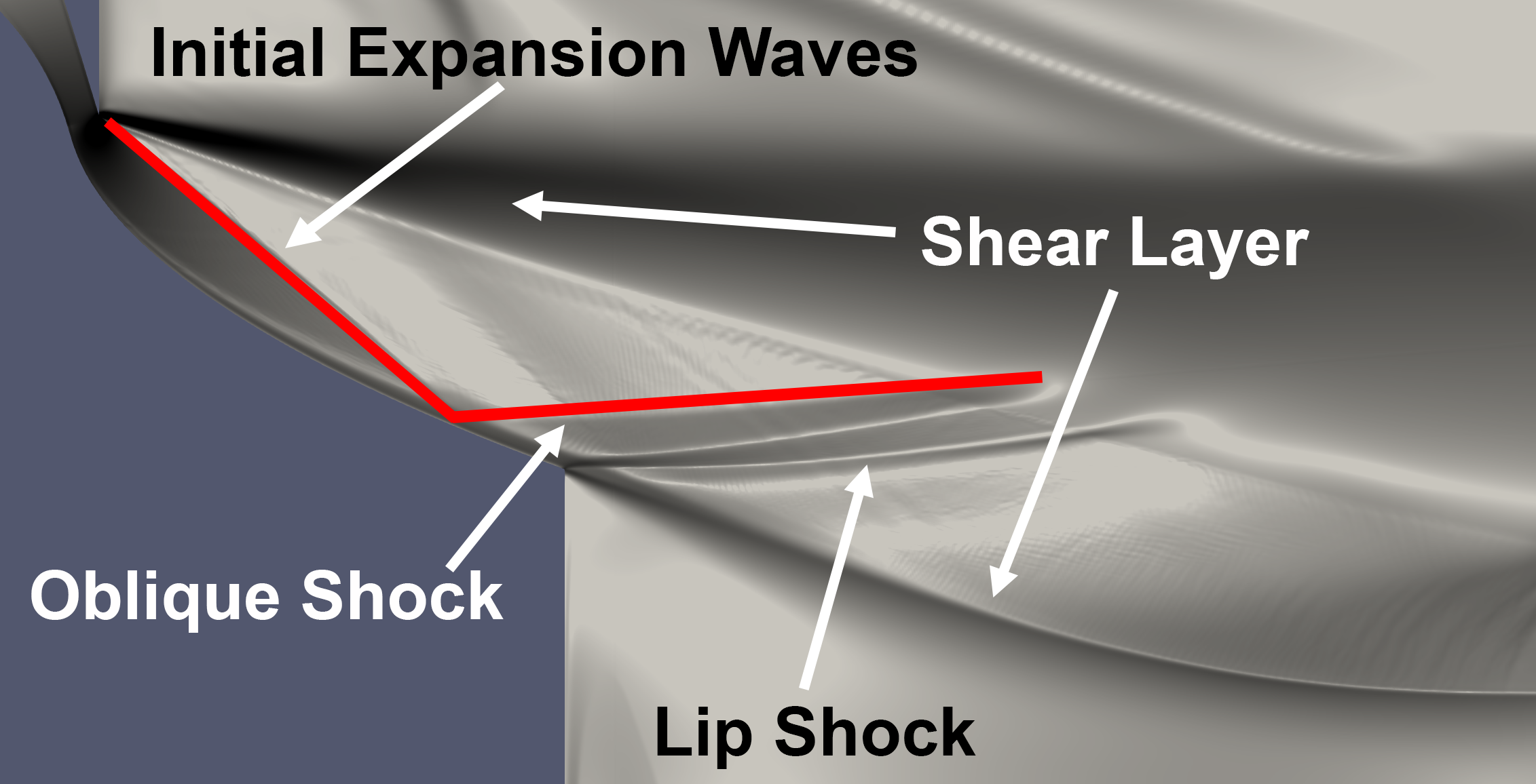
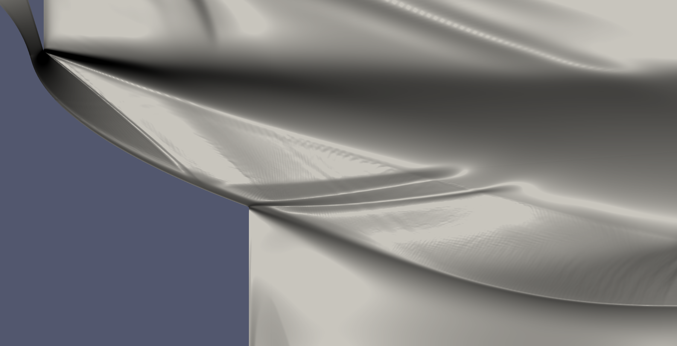
CFD Results - Schlieren
A numerical Schlieren plot was created by taking the first derivative of density with respect to space in order to study the flow features. The flow features were compared against past experimental data and the results matched up closely. Unlabeled and labeled Schlieren diagrams can be found below.
Key flow features expected were present,
- Open-wake formation
- Oblique shock
- Lip shock
- Shear layer
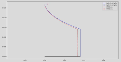
CFD vs MOC
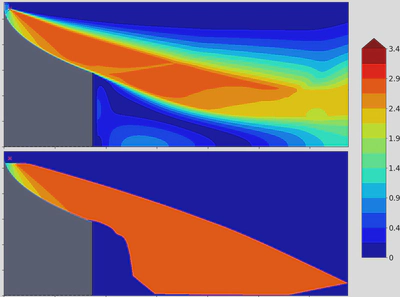
High fidelity, low speed CFD results were used to validated the low fidelity, high speed Method of Characteristics (MOC) used for iterative optimization.
Aerospike vs Bell Nozzle
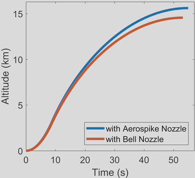
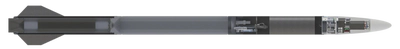
Implementing an aerospike in the UTAT rocket ‘Defiance’ would result in a 7.2% increase in apogee from 14.4 km to 15.6 km.
Cooling System
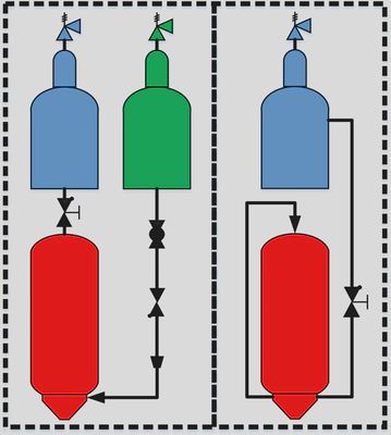
N2O can serve as a coolant due to its high vapour pressure at room temperature (4.8 MPa) and available heat of vaporization
Active cooling
- Copper nozzle due to high heat conduction
- Coolant flowrate sized to keep nozzle below 700 K
- Feasible if planned total firing time > 40s
No cooling
- Graphite erosion rate: 0.03 – 0.05 mm/s
- Re-usable 3 to 5 times at 4 second burns
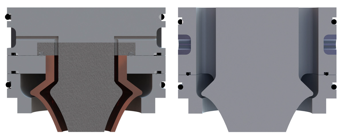
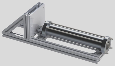
Mechanical Design
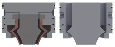
A copper nozzle with 6mm cooling channels, and a graphite nozzle with no channels were designed.
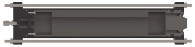
A N2O-Paraffin lab scale hybrid engine was designed to test the nozzle.
Environmental Analysis
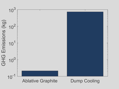
- N2O, with a GHG equivalent 265 times higher than CO2 results in the bulk of GHG emissions when used for dump cooling.
- An optimal firing time will produce steady state test data while reducing GHG emissions.
Conclusion
Manufacturing of nozzle and engine components and testing to be carried out by UTAT.
Emerson Vargas Niño
Aerospace Engineer and Educator
Developing advanced solutions and leading multidisciplinary teams